


BornSinner
-
Posts
4,065 -
Joined
-
Last visited
-
Days Won
3
Content Type
Profiles
Forums
Gallery
Store
Events
Posts posted by BornSinner
-
-
Tom Cruise is a great rider.........

 :fruit:
-
Kyle
do you guys have Parts Unlimited Account????
-
I was the stunt rider on the train........hahahahaha
-
I heard he is going to be shooting another bike scene like MI2...."That is real"...just like Torque....
 :roll::roll:
 -
This How-To write up was done by "05zixxer". This was done on a 05 zx10r, but this can be done on other bikes.
First, you have to open up the garage door opener (gdo) and find the switch. Solder on a wire on each side of the switch and close up the gdo body. I cut the plastic away a bit to allow the wires to go through the body easier. (there are no pics for this since I figure this part depends on what gdo you have)
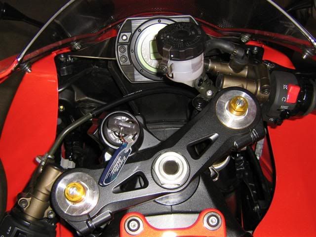
Next, locate where you want the gdo. I put mine under the seat.
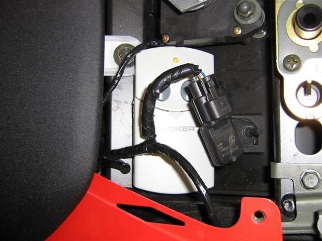
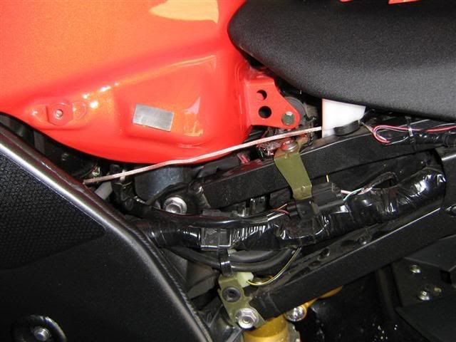
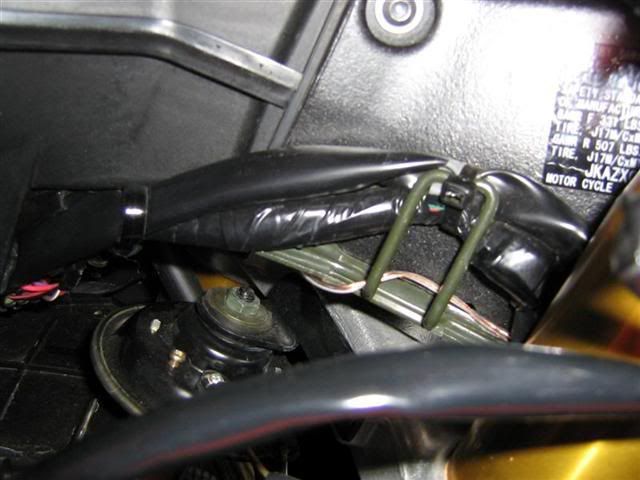
Now, run the wire through the frame and fairing to wherever you want the switch. I used thin speaker wire (cant remember the exact guage) because it's easy to route and is not very heavy:
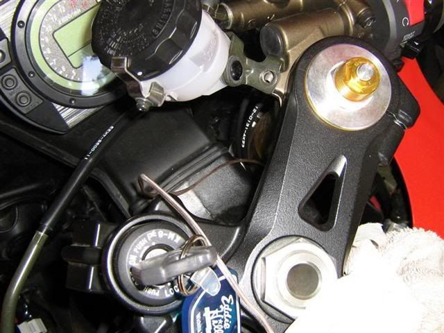
Next is the switch. I didnt want to hack into my controls, so I made a bracket out of mild steel, drilled and painted it and mounted the switch from Radio Shack (p/n 275-644) on it to complete the install.
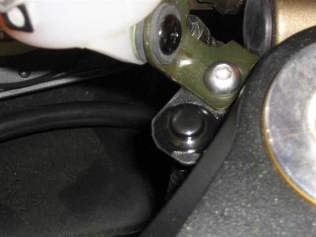
Now I dont have to fumble around trying to find the button through my jacket.
-
Cause Ohio people are smart asses
-
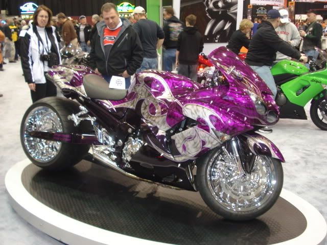
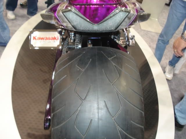
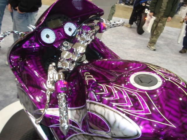
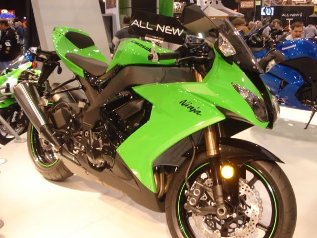
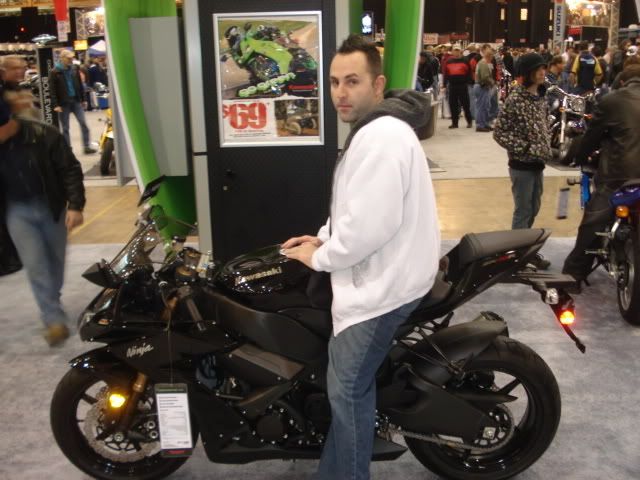
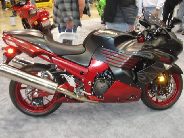
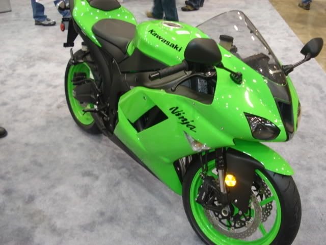
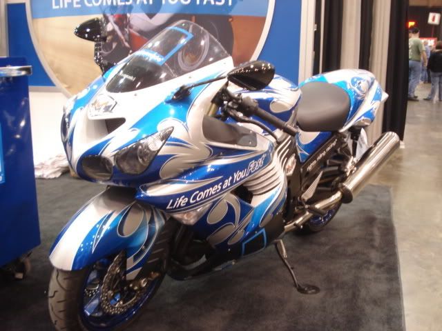
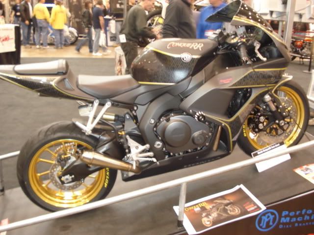
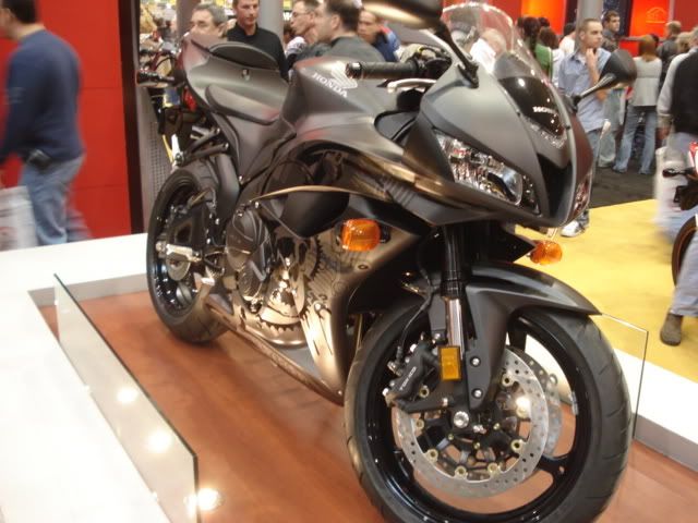
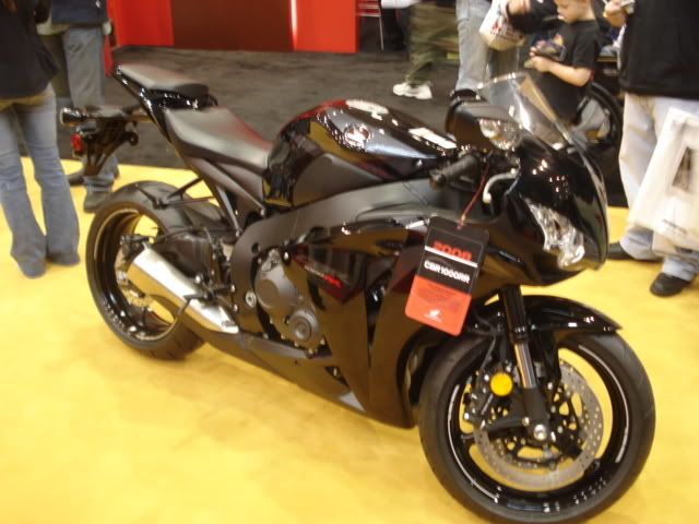
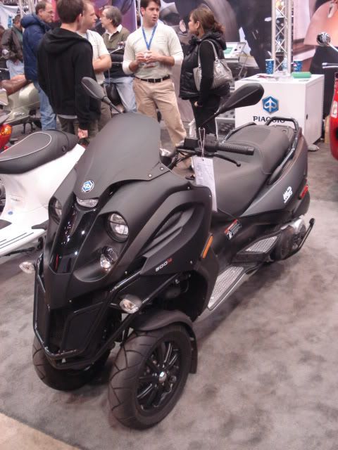
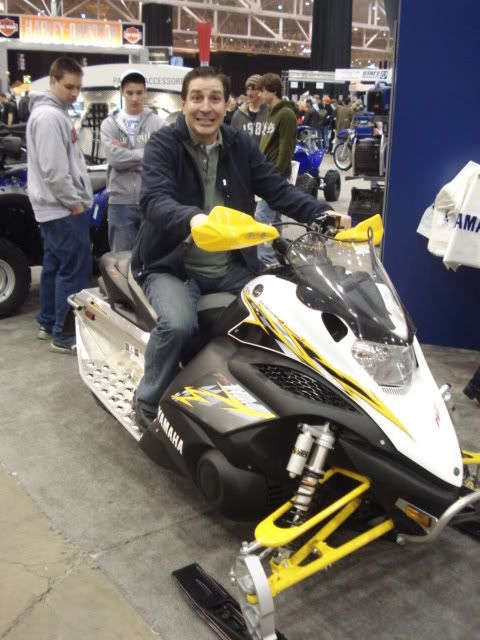
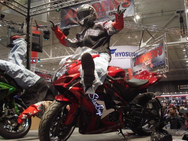
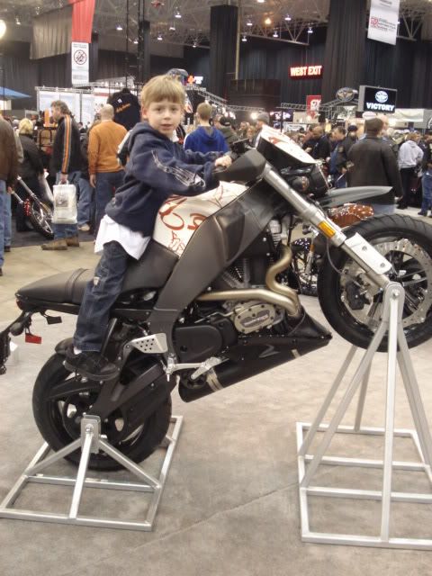
Here are some of the picture we took.
BornSinner, Satan, Bananas + M, CBRgirl, gsxr750chic, and "Timber" (hahaha)
Damn this took a while to post...ENJOY:banana:
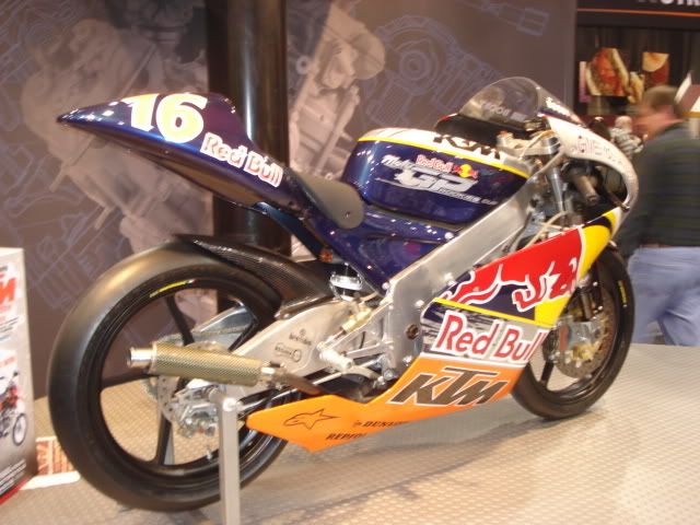
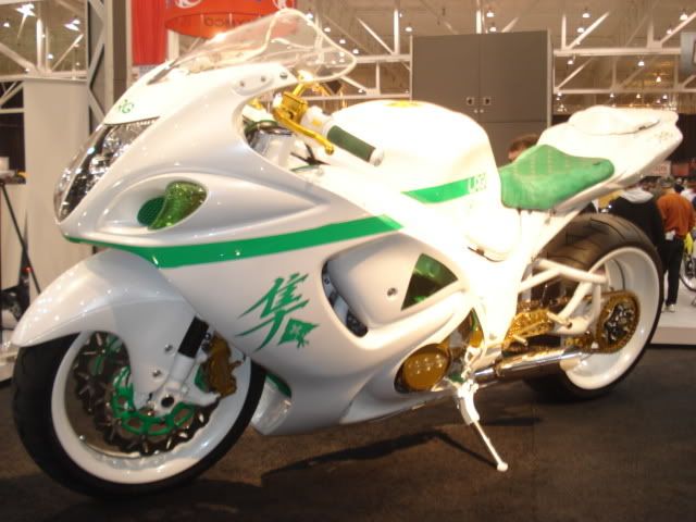
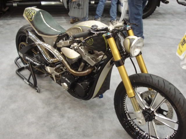
KTM
KTM by Jesse Rooke


Kawaskai
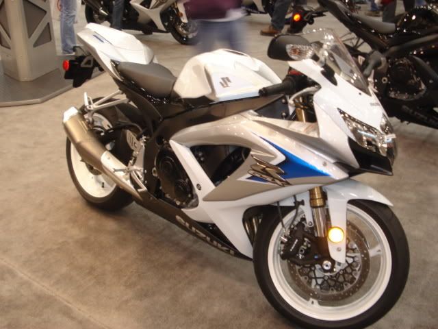
Suzuki
Misc Mule(...Not Bananas)
Honda
These guys not OHIORIDERS...but I think they ride "something else":D
Yamaha
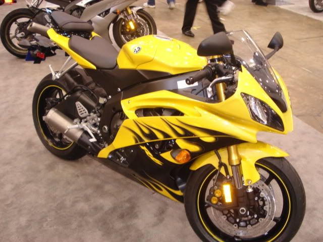
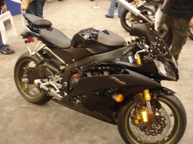
I have Video of the McCoys Boz Bros R1...need to post it
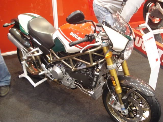
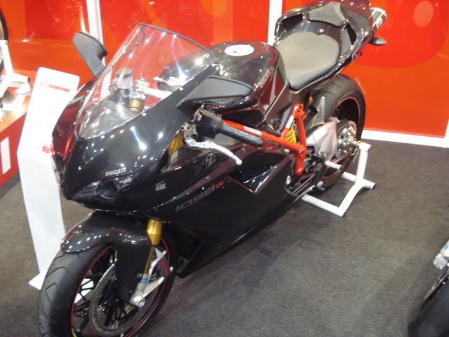
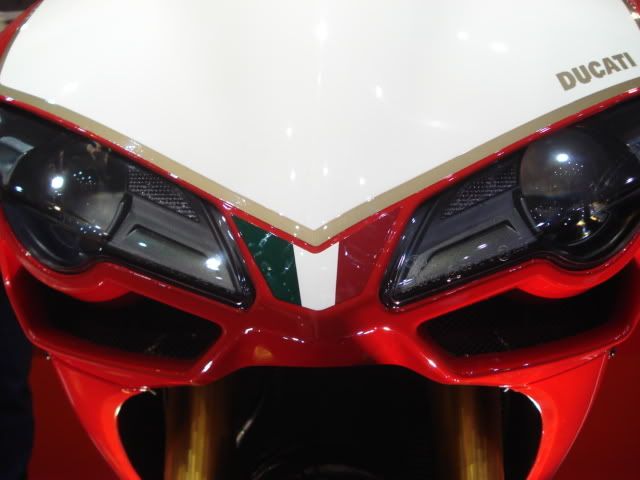
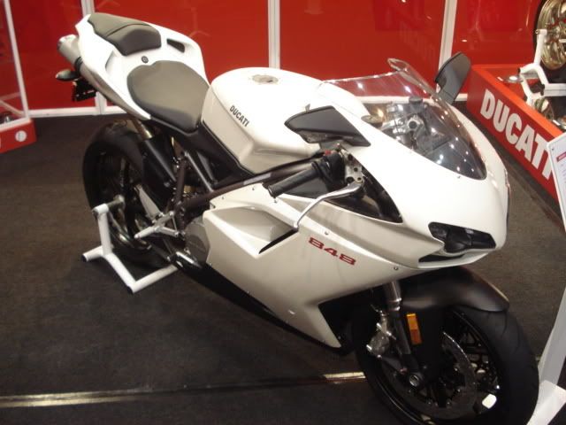
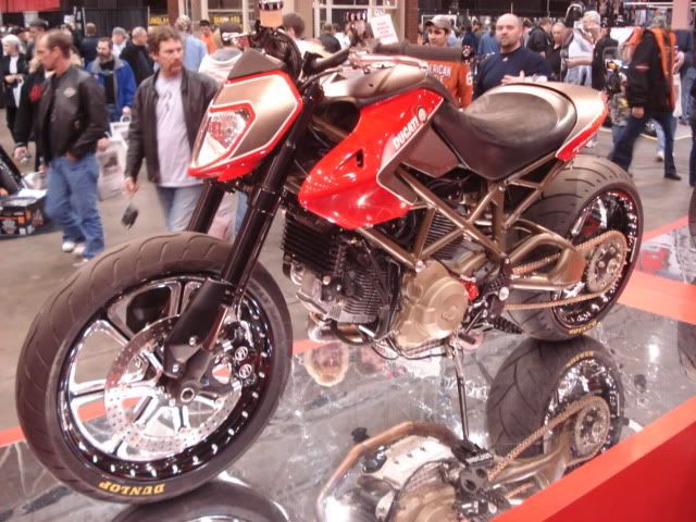
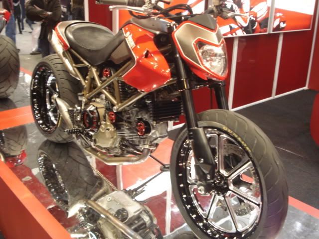
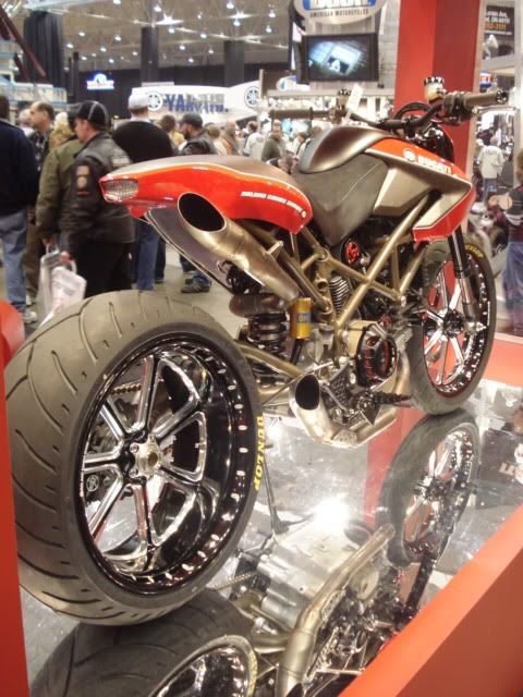
Ducati
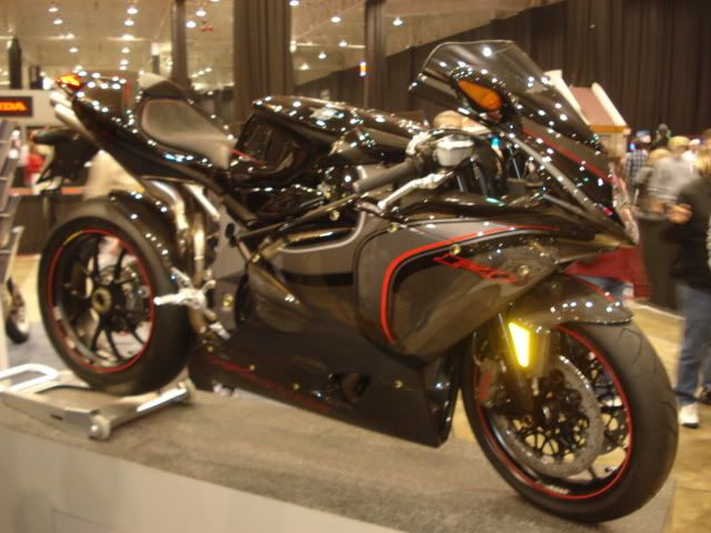
MV
Misc Pic

Augrish...these kids are coming for you....

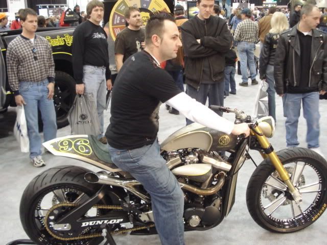
Another Roland Sands bike...but you can sit on this one
-
I have a cool helmet cam ....my chaine broke last year and flew up and hit me in the head"cam" fuked it up good .I got another one . I plan on riding w/ it all the time this season.
Do you still have the ant?
Are you talking about the rear view camera? (ANT)
If so ...yes
I just got a bigger screen, I really couln't see the object that good be hind me.....
But I will now
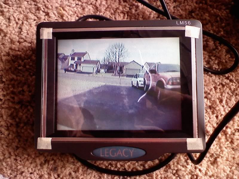
Its getting painted right noe is that it matches the bike.....
-
Doesn't the foot peg have a detent that keeps it from flapping around? I bemlieve the passenger pegs will lock into place.
my pegs lock...so i dont see it bouncing around...also i look for something that will record....im not shooting a road race or stunt vid....plus if something happens to that camera...oh well....but thanks for the feed back...
-
Advice...
Please don't add music to every video, it's so cliche. The sound of the bike banging through gears is the best music of all.

:DAdvice taken:D
-
I do have partial hearing loss.
WHAT!!!!!!!!!
-
I will when the weather breaks.
-
This How-To was written by "Diderr"
This is a write up that I will be doing but with a different camera set-up.
http://www.youtube.com/watch?v=M7tp3-yN7dA so i was messing around and figured out a good idea for a cam mount.
Supply list:
(1)- 1/4"-20-1" screw (most cameras take this thread)
(2-4)- 1/4" washers (depending on screw size)
Tool list:
power drill
17/64 drill bit (again depending on your screw size)
flat or philips head screw driver
adjustable wrench
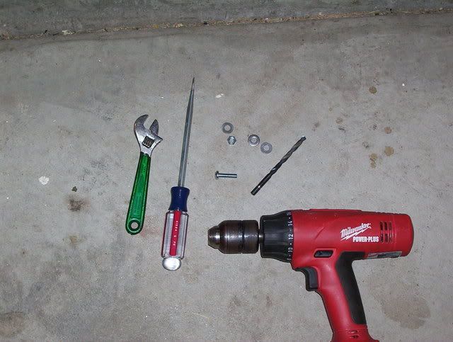
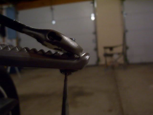
drill a 17/64 hole in your passenger peg. where the hole goes depends on camera threading position and personal preference. the hole is barley big enough to get the screw through, I did this to insure a tight hold.
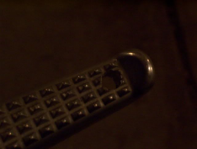
insert a washer on the screw, then poke it through the hole, put on a nut, and tighten.
add shims ( left over washers ) so that that your camera sits tight and in your desired position.
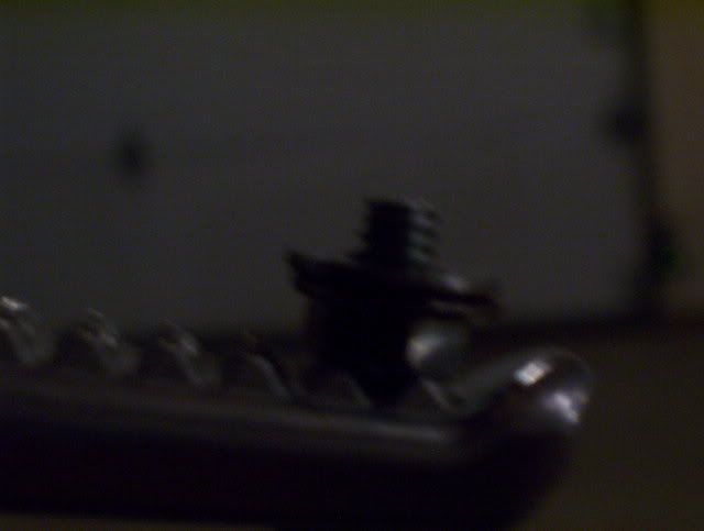
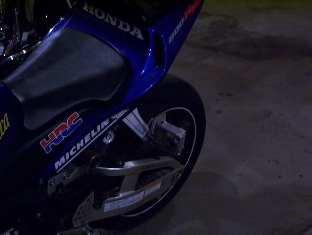
thread cam on, all done!!!
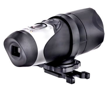
This is the camera that I will be set-up
-
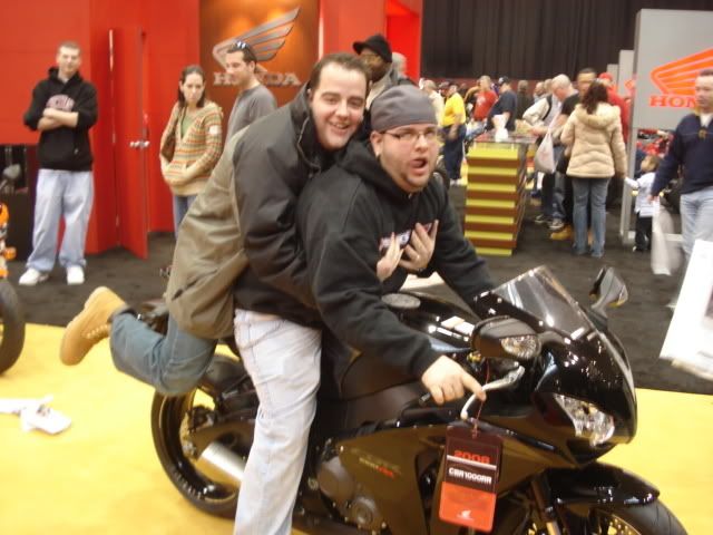
:lol:Satan was ALL over IT.....
-
Welcome Mr. CAPS
He must talk really LOUD!!!!
:D -
 I see that Satan fixed it so Nobody can use it now......
-
He Is Yelling At Us.....he Is Sooooo Happy To Be A Member !!!!!!!!
 ;)
;) -
Welcome to OhioRiders
V TWINS Rule
-
Welcome to OhioRiders
Have fun....
-
I made some awhile back but decided not to install them. I used the other method and not the CCT.. Whitey, Im sure you know what the other method is.
here was my test unit that I built..
[ATTACH]118[/ATTACH]
I made a set of those too....
But they not that bright, and you run the chance of melting them....
-
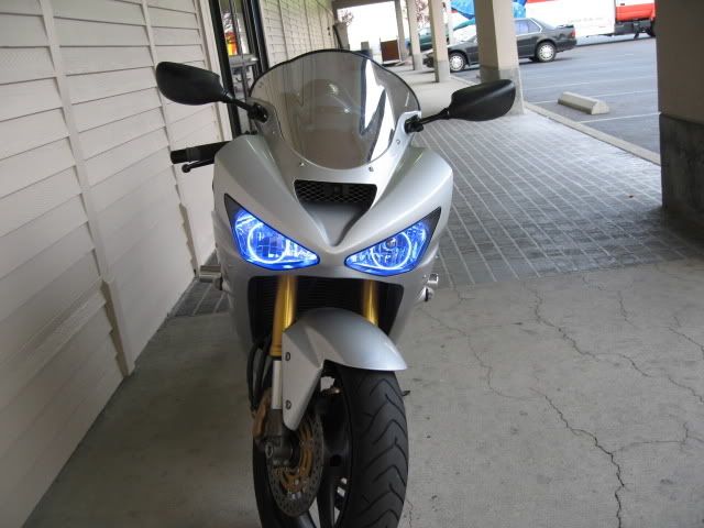
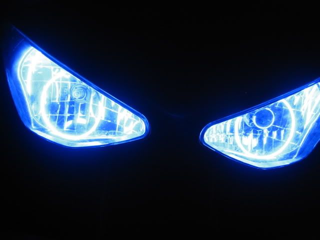
For people who know me or my bike, I have a lot of LEDS throughout the bike. So you know I would post something up about LEDS or lights. This How To was done on a 03-04 636 and was done by "Minguezcd" from other forum. I know that not everyone ride a 363 but this How To could be used for other types of motorcycles.
There are people on Ebay selling the same rings for around $120.00
These ring dont melt when you run your high beams for a long period of time.
The CCFL rings I also found them in 120mm on the intnet.
Required hardware
- Heat source...heat gun or oven
- 2part glue aka CA clue (available at hobby stores)
- Drill
- Hot glue and gun
- Silicone (like the type used in bathrooms but black)
- switch or relay (depending on how you want to turn it on)
- Black spray paint
- 80mm CCFL ring - http://www.xoxide.com/blucolcat80f.html
- Panal popper/flat head screw driver/
Step 1 - Remove your front fairing (i hope i dont have to go into a detailed how to on this)
Step 2 - Remove your head light. 4 bolts in each corner and dont orget the wiring harnesses
Now that the easy part is done...
Step 3 - Taking apart your head light... Some use the "bake" method..i used a heat gun. Your headlight is 2 pieces held together by hot glue. The back which is black ABS plastic, the the front which the clear lens. Heating up that glue will allow you to pry apart the 2 pieces. I used a panal popper (car install tool) but a flathead will work also. Be careful with the heat...the head light is ABS so too much heat can damage the head light.
Step 4 - Get the fan with CCFL ring and remove the CCFL from the fan. The CCFL ring is surrounded by plastic that allow it to mount to the fan. REMOVE THIS PLASTIC. It will melt in your head light. (I learned the hard way) All you want is the glass CCFL ring and blue transformer from the package.
Step 5 - The wires leading to the CCFL ring are white....This is an extra step...but I painted the wire, and a portion of the ring black spray paint to create a more aggressive look and hide the wires.
Step 6 - Get the 2 part glue. WARNING - if you got the right glue, you have one chance at this! Postion the 1st ring to where the top and bottom of the ring sit at the edge of the chrome headlight insert and centered as best as you can around the bulb (wires on top). Using the glue, put a small dab on the ring and chrome insert. Be careful on to let it drip into the head light. The easiest way to avoid this is to place the headlight assembly on a table with the headlight sitting as it would on the bike. Once that dab is there, spray it with the activator. If your aim is questionable, place a rag over your bulbs is you left them in. Do the same to the top.
Repeat to the 2nd side
Step 7 - You will need to drill a hole in the back of your headlight to run the wires through. The wires should be long enough to mount the transformers (little blue boxes) outside the headlight. I whought about mouting them inside, but was concerned about heat. After the hole is drilled and wire run through, seal it with the silicone. Allow some time for the silicone to dry.
Step 8 - Mounting the transfomers. You have a couple different options, you can cut and extend the wire and mount thetransformers somewhere in the side fairings....but i mounted them behind the headlight.
Step 9 - Putting the headlight back together. This is when a heatgun works better than the over. Reheat the glue on both parts and slowly press back together using the hot glue gun to seal any areas that might need it.
Step 10 - Wiring - I wired mine to my Pager for my alarm using one of the outputs and a relay because i didnt want to mount a switch. I also rewired my headlight so my lowbeams would be hedlight off, and high beams would be low and high both on. For me this worked fine because i ride with my high beam on regardless. When running the power wires, I reccomend using some type or male/female crimps so you can easily disconnect if you should ever need to remove your headlight.
-
Bananas has all the pic I took...I will try to get them from him ASAP
-
Im working on a new design
-
as a safety word...thats a BIG WORD
Tom Cruise and waste of a good bike.
in Daily Ride
Posted
But he had the cool jacket and glasses